
Think K&K with balanced string output and without the feedback!
The James May Engineering (JME) Ultra Tonic Pickup (UTP) for steel string guitars is a passive, brideplate-mounted, soundboard transducer (SBT) pickup with on-board feedback suppression. James is also a partner in Audio Sprockets, creators of the ToneDexter and ToneDexter II.
For those who may have a K&K Pure Mini already installed, JME has a special pickup system that will allow you to convert it to the Ultra Tonic in order to benefit from the improved 1st string response, feedback supression, and Volume Control.
An additional pickup model is available specifically for nylon string guitars.
An Under-Saddle Transducer, or UST, is comprised of piezo crystals housed in a thin ribbon. It is laid in the saddle slot of the bridge, the saddle rests atop the UST and the strings press the saddle tightly against the pickup. The saddle is the only material separating the pickup from direct contact with the strings.
By contrast, a Soundboard Transducer, or SBT, is comprised of piezo crystals often embedded in one or more rectangular, triangular, or disc-shaped modules. The module or modules are typically attached to the bridgeplate inside the guitar. In addition to the material of the saddle, the remaining material of the bridge beneath the saddle, the material of the soundboard, and the very bridgeplate itself sit between the strings and the pickup. As a result, SBTs are highly regarded for their ability to approximate the sound of an acoustic guitar in an amplified setting, often with much less piezo “quack” than Under Saddle Transducers (USTs).
In my experience, as good as they sound, SBTs have been more prone to feedback than their under saddle siblings, especially at higher volumes. Apparently, this is due to their tendency to co-mingle the lower frequencies produced by the acoustic instrument. This is commonly experienced as an overall boomy or muddy sound.
A common shortcoming that plagues both an SBT or UST install on an acoustic guitar is the quiet high E
, where the 1st string produces less volume than the other 5 strings, even after careful positioning or re-positioning of the pickup(s).
The JME UTP addresses these two common drawbacks associated with USTs and SBTs:
Presented, below, are three back-to-back recordings of my 1976 Guild F-512. The first clip is recorded through a Shure KSM141 microphone alone, as a reference. The second clip is recorded (directly) through an LR Baggs Anthem pickup. The third clip is recorded using a (newly installed) JME UTP V3, the signal ran through an Audio Sprockets ToneDexter trained with that same Shure KSM141 microphone.
I can appreciate the big, boomy sound of most modern pickup systems, but I happen to prefer an amplified sound that more accurately represents the sound of my un-amplified instrument, only louder. As sound volume increases, I have had to face the pragmatism of controlling feedback, and understand any and every acoustic guitar amplification system to be a compromise, juxtaposing my preferred sound with the greatest feedback potential. I have subsequently encountered and/or pursued (nearly) every pickup system available, investing much in time and money, and am convinced of the following fundamentals:
my guitar, only loudersound
my guitar, only loudersound
Proper placement of an SBT is much more critical than installing a UST. Think location, location, location. Some installers have chosen to test fit an SBT using a double-sided tape as, once it is secured with glue, it is pretty much there to stay. It had better be in an acceptable, if not optimal, location.
Three methods I have used for locating and applying SBTs:
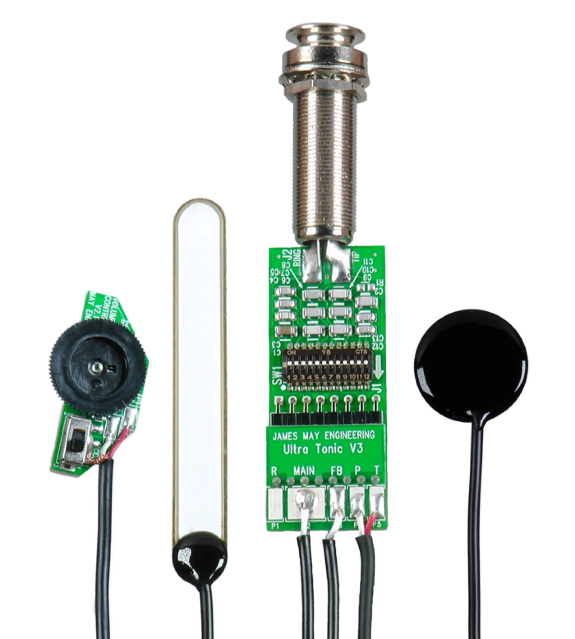
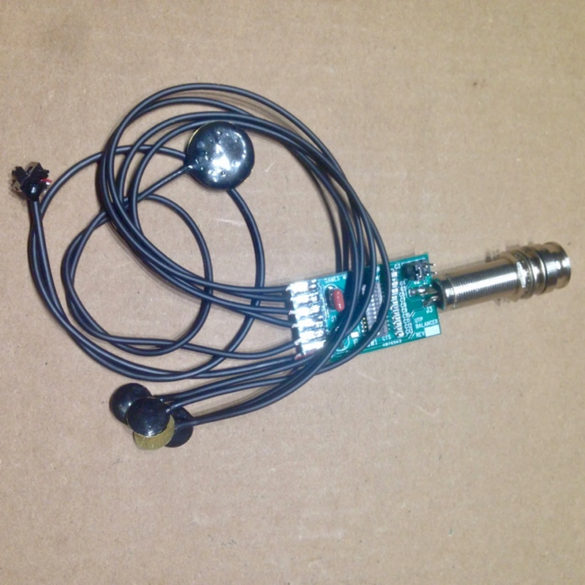
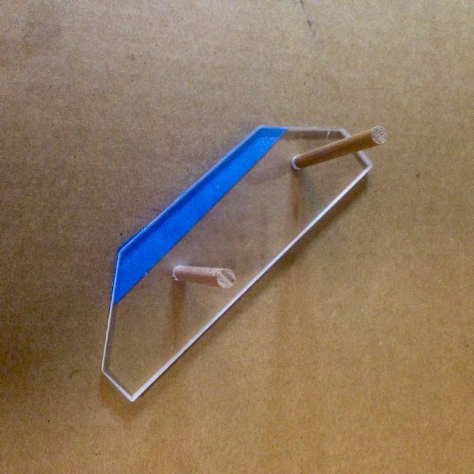
The most recent version of the Ultra Tonic pickup, Version 3, includes 2 separate sensors to affix to your guitar's bridgeplate. The main pickup is a long, slender plate (10 x 72mm) that is designed to be positioned directly beneath the centerline of the saddle in order to best capture desirable string response.
Additionally, a single, 21mm disc
-style sensor is required that provides additional information to help control feedback. This sensor is deliberately out of phase with the main sensor and captures less-desirable top plate resonances. It is to be attached to the bass side of the bridgeplate, away from the main sensor.
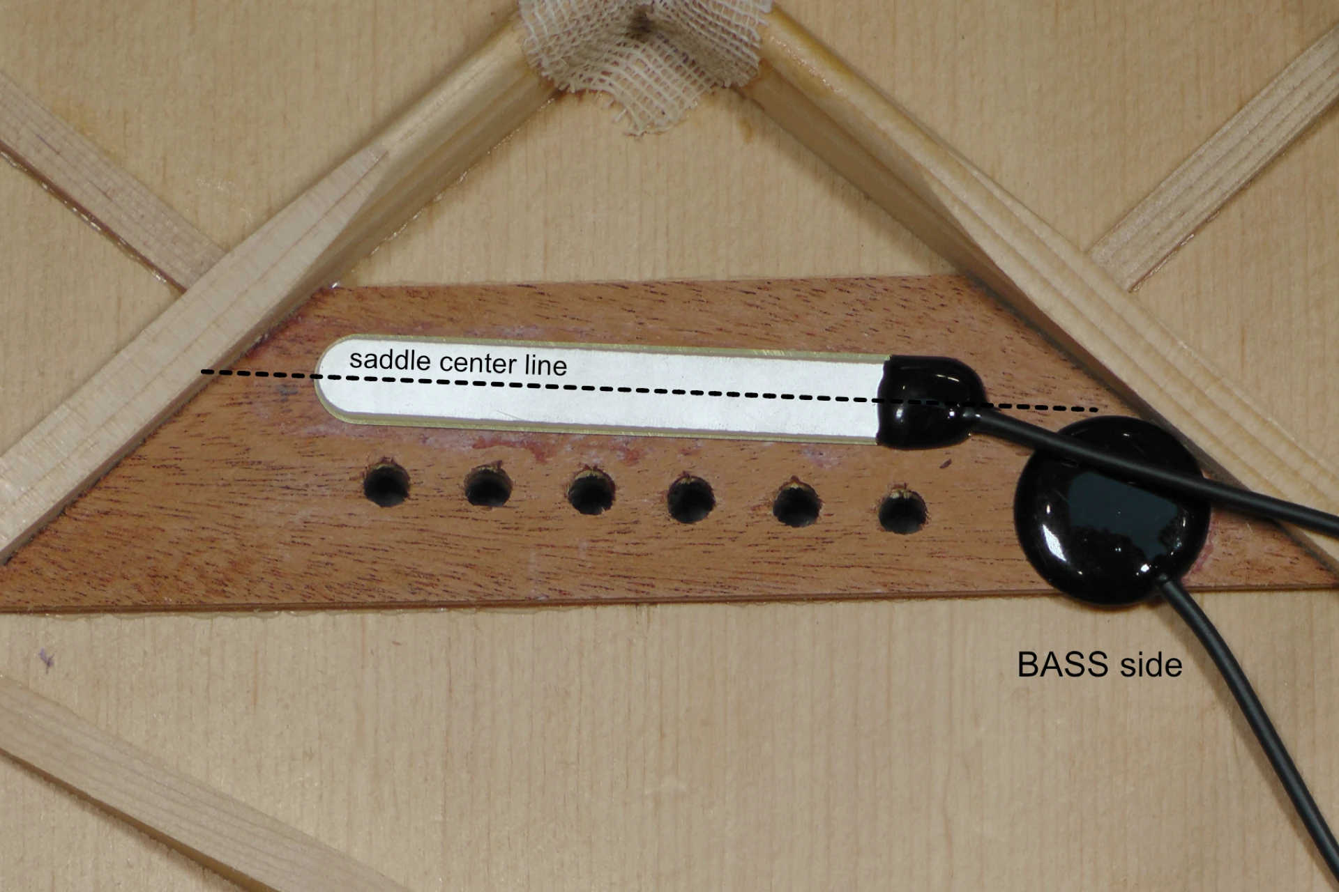
Positioning the Sensors (photo courtesy of JME)
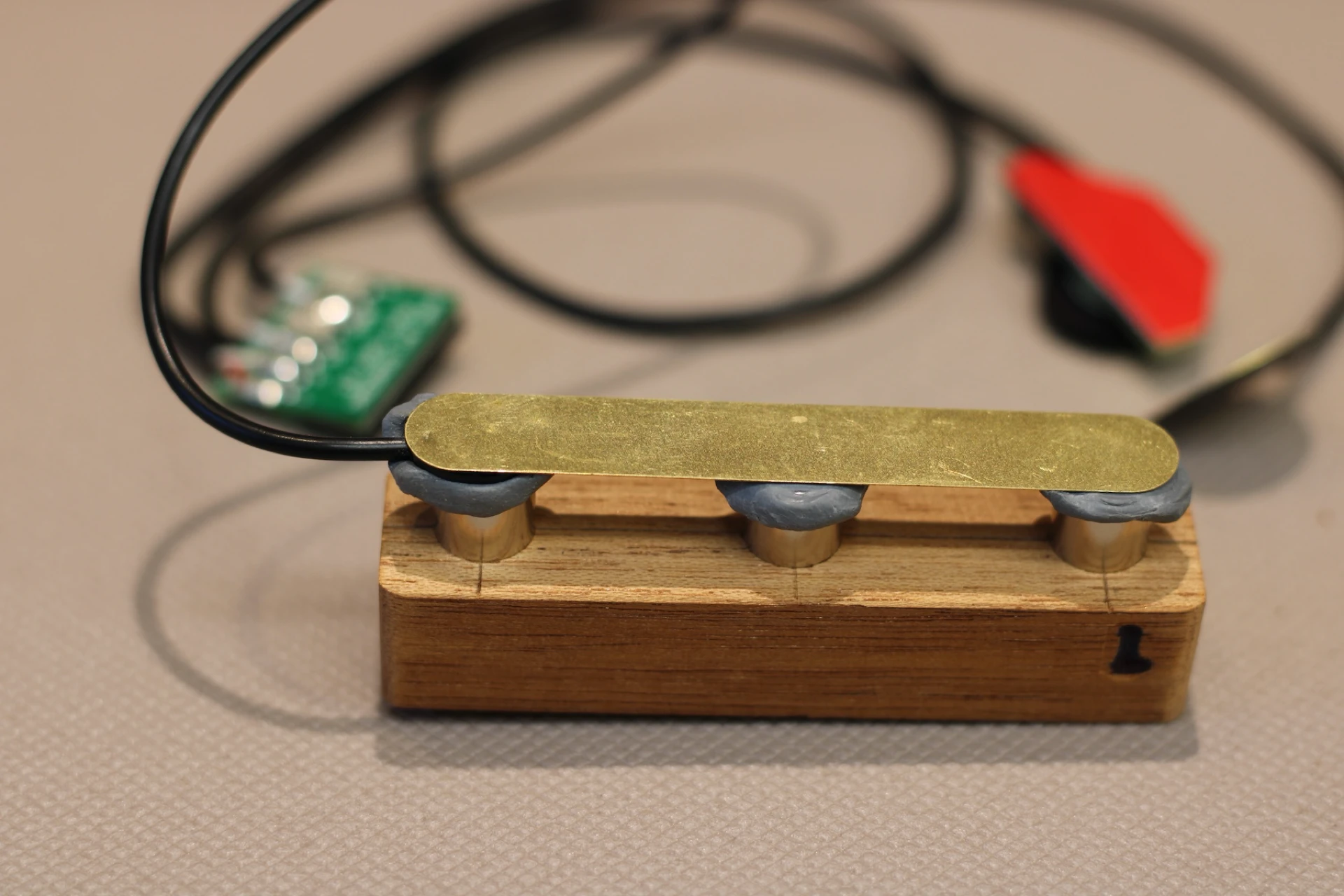
I installed the UTP V3 in a Gibsom Hummingbird using a custom jig after the Magnet and Putty method. Six cylindrical magnets are suspended in two wooden blocks, three magnets per block. The primary purpose of the wooden block is to prevent the strong magnets from attaching to one another.
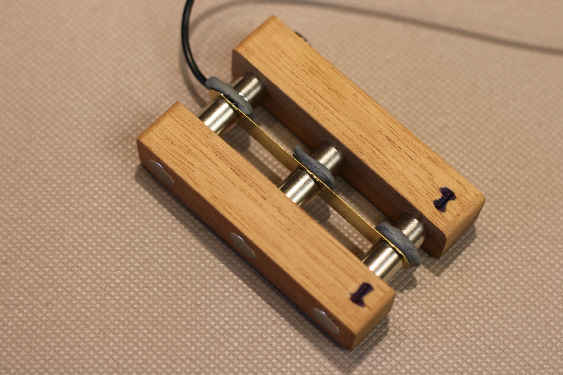
JME UTP V3 and Magnets
The main sensor (plate) is temporarily held in place on one of the Magnet blocks using putty.
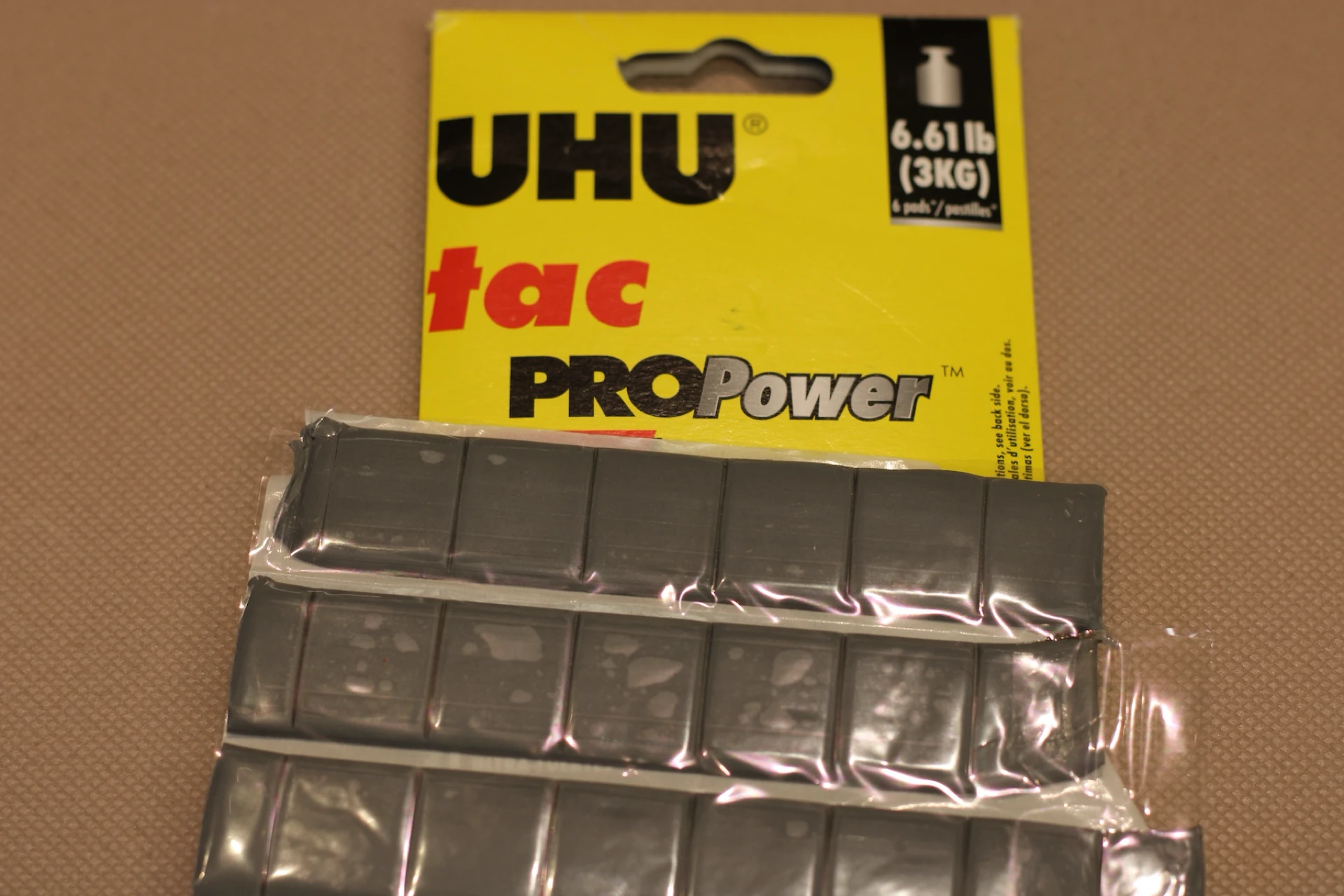
Putty for Magnets
JME UTP V3 Ready to Install
This particular guitar already had two holes drilled through the bridge at each end of the saddle slot. These holes provided me with the perfect path for the main sensor to be aligned with when I glue it in place.
Hummingbird Bridgeplate
One half of my magnet jig is going to rest on the bridge, directly above the saddle slot. This jig will serve to both align the sensor with the saddle slot as well as "pinch" or "clamp" it in place against the bridgeplate.
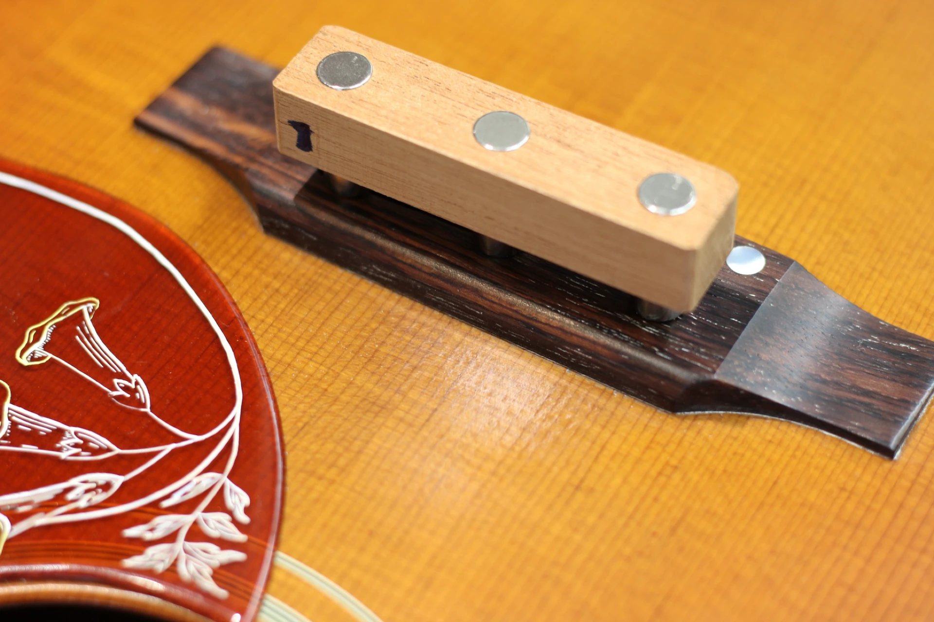
Magnet Jig Outside
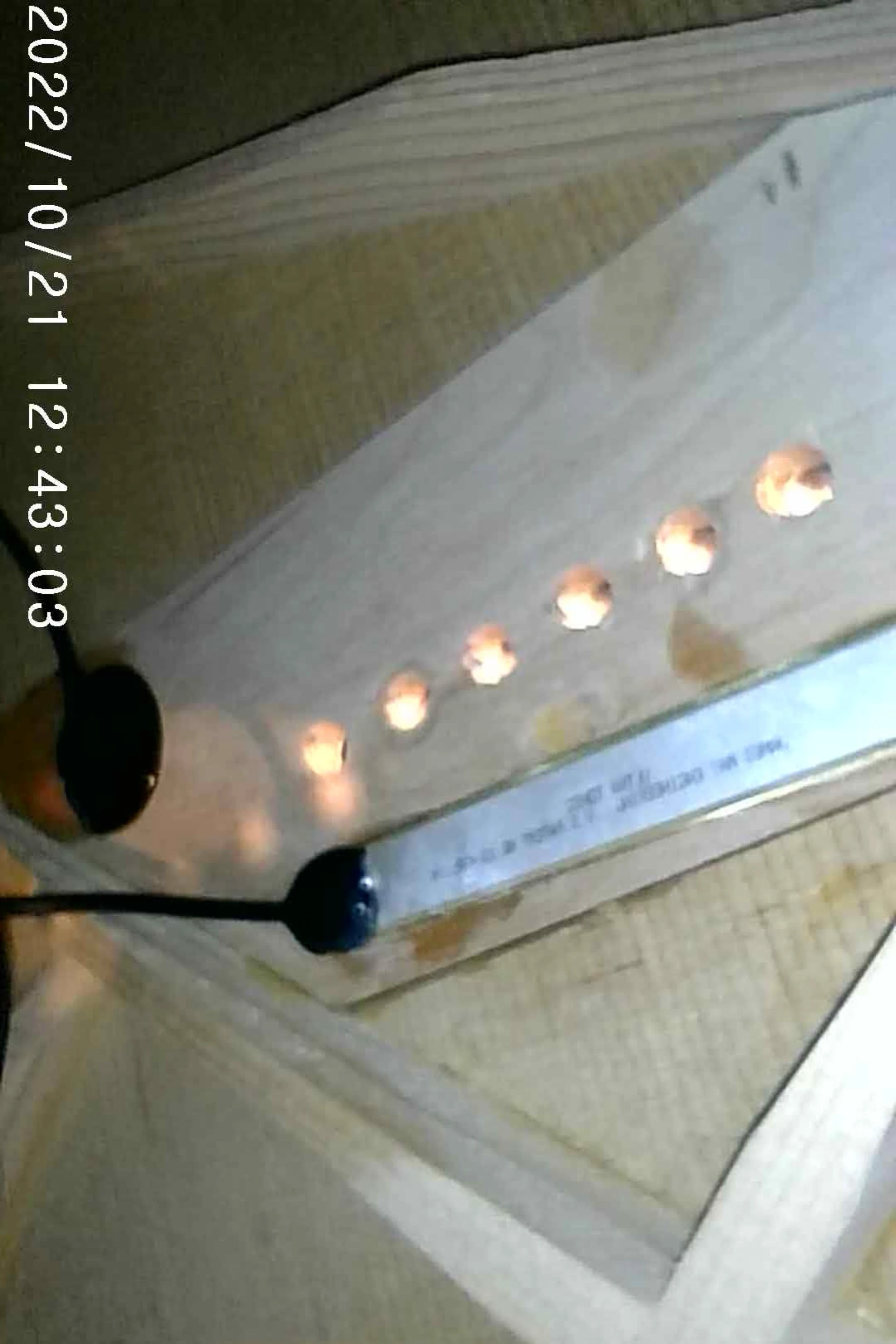
After conducting a "dry run," positioning the sensor in place without any glue, I smear a gel CA glue onto the sensor. With one hand I carefully place the jig with the sensor inside the soundhole. With the other hand I hold the mating half of the jig atop the bridge directly over the saddle slot. As I get the jig holding the sensor close to the bridgeplate I begin to feel the pull of the magnets. I let them guide me into place, and quickly verify the positioning before leaving the magnets to hold things together while the glue sets.
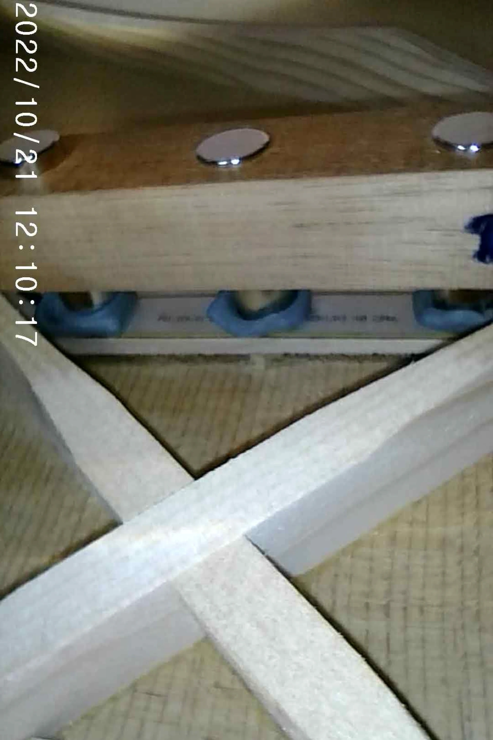
Magnet Jig Inside
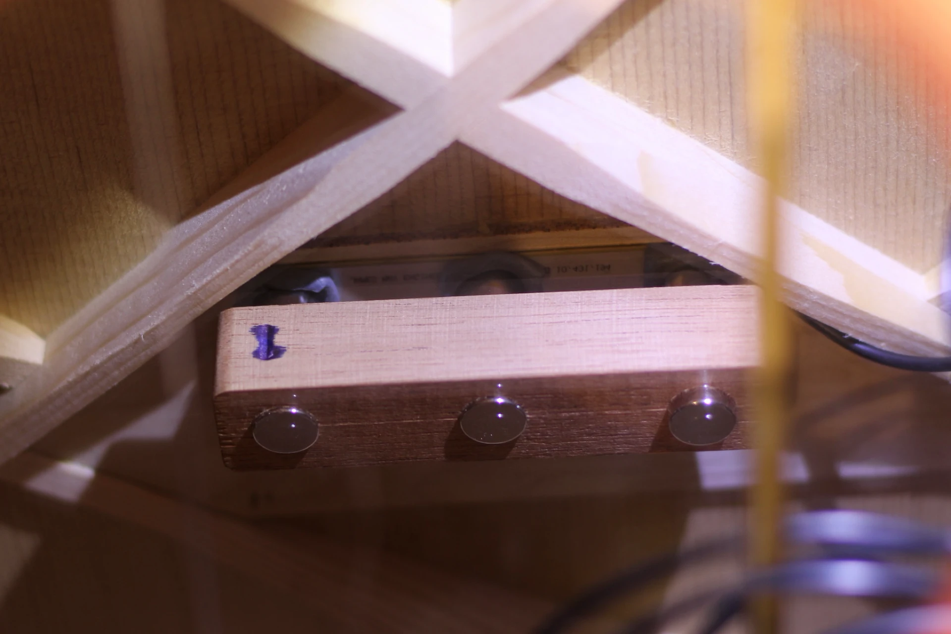
Magnet Jig Inside
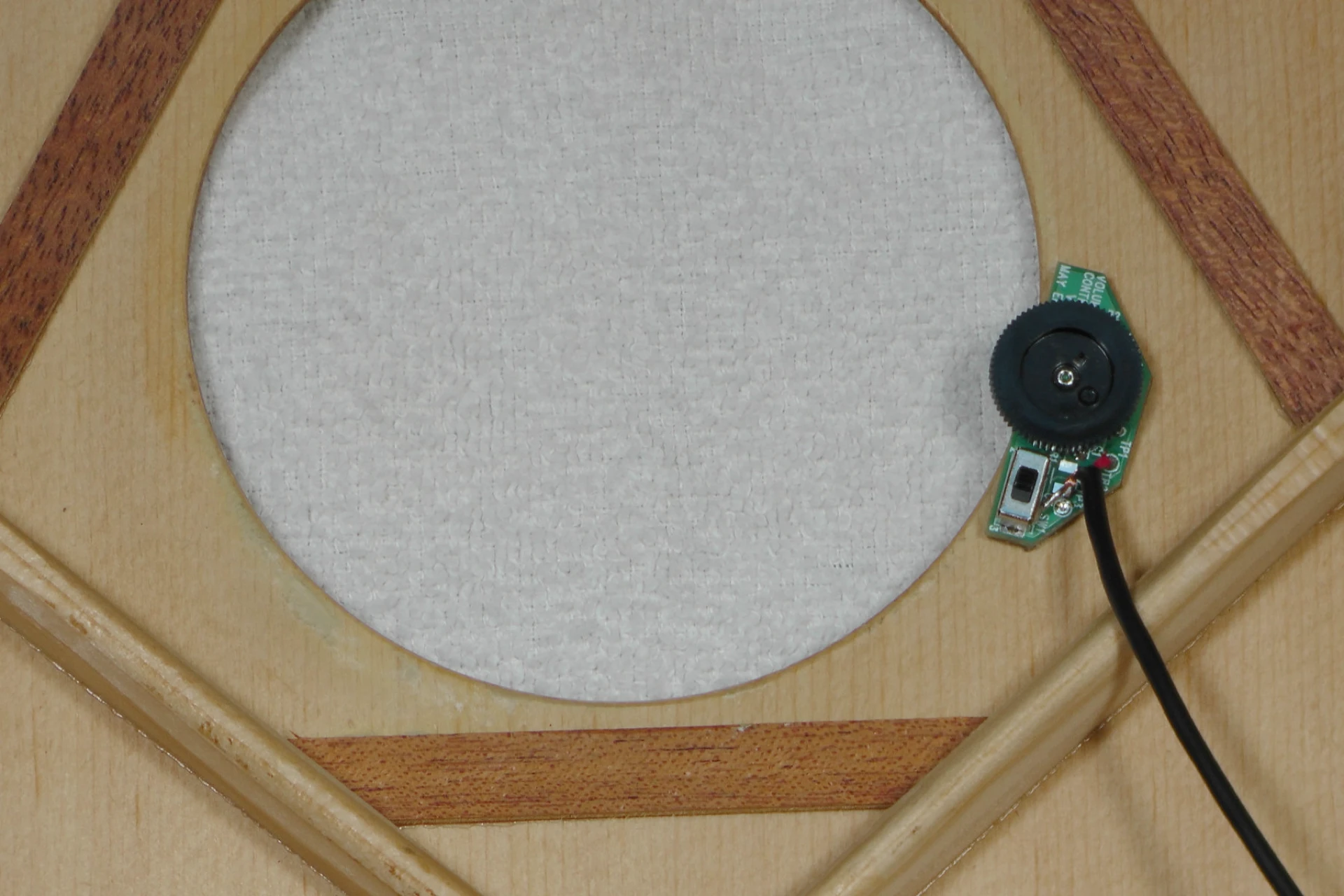
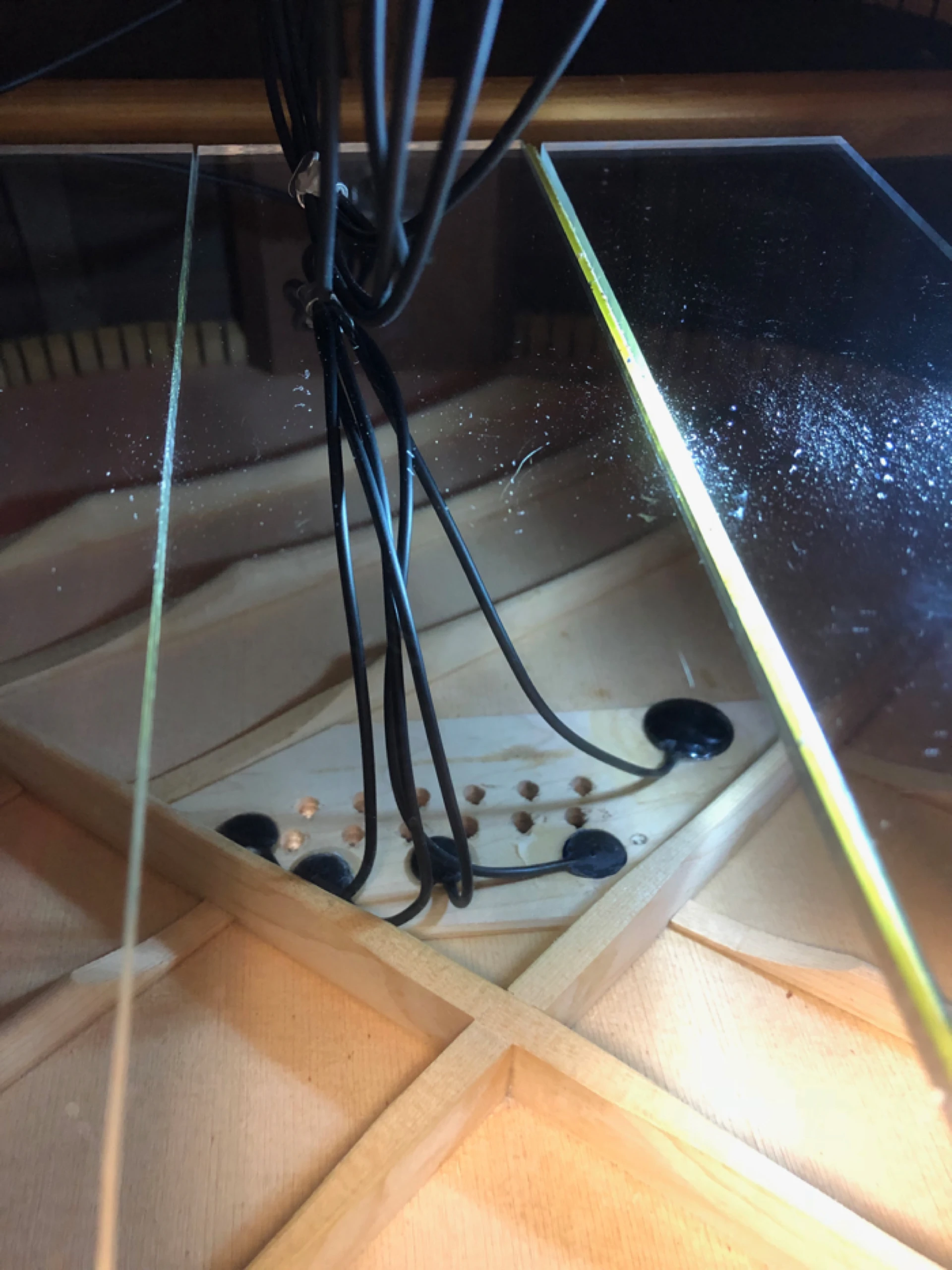
The "Body" Sensor, the disc-like sensor that is used to assist with controlling the potential for feedback, is easily positioned toward the back edge of the bridgeplate (closest to the tailblock), on the bass (6th string) side. If you are accomplished, this sensor can be placed by hand. If you need assistance, you can use a single cylindrical magnet with putty to position the disc inside the guitar, and hold it there while the glue dries with a second magnet carefully resting on the soundboard, behind the bridge. The CA glue dries fairly quickly, so i am able to carefully remove the jig(s) from the guitar, leaving the sensors installed.
Sensors Installed
A soundhole mounted volume wheel rounds out the offering, and is no small accomplishment. As you may be aware, attempting to alter the volume in a passive pickup system while maintaining tonal balance has been an elusive chase. The Ultra Tonic pickup has overcome this issue by employing cable capacitance compensation. If needed, a small switch is accessible which will disable the compensation when the pickup is used with a wireless system.
JME UTP V3 Volume Control (photo courtesy of JME)
Balancing the signals, and thus controlling feedback potential, is accomplished via a small circuit board that is directly mounted to the 1/4 inch endpin jack. There are 12 DIP switches, one of which will be switched to the "On" position during the setup process, depending on the particular characteristics of a given guitar. The complete system is minimalist, battery-less, and very lightweight.
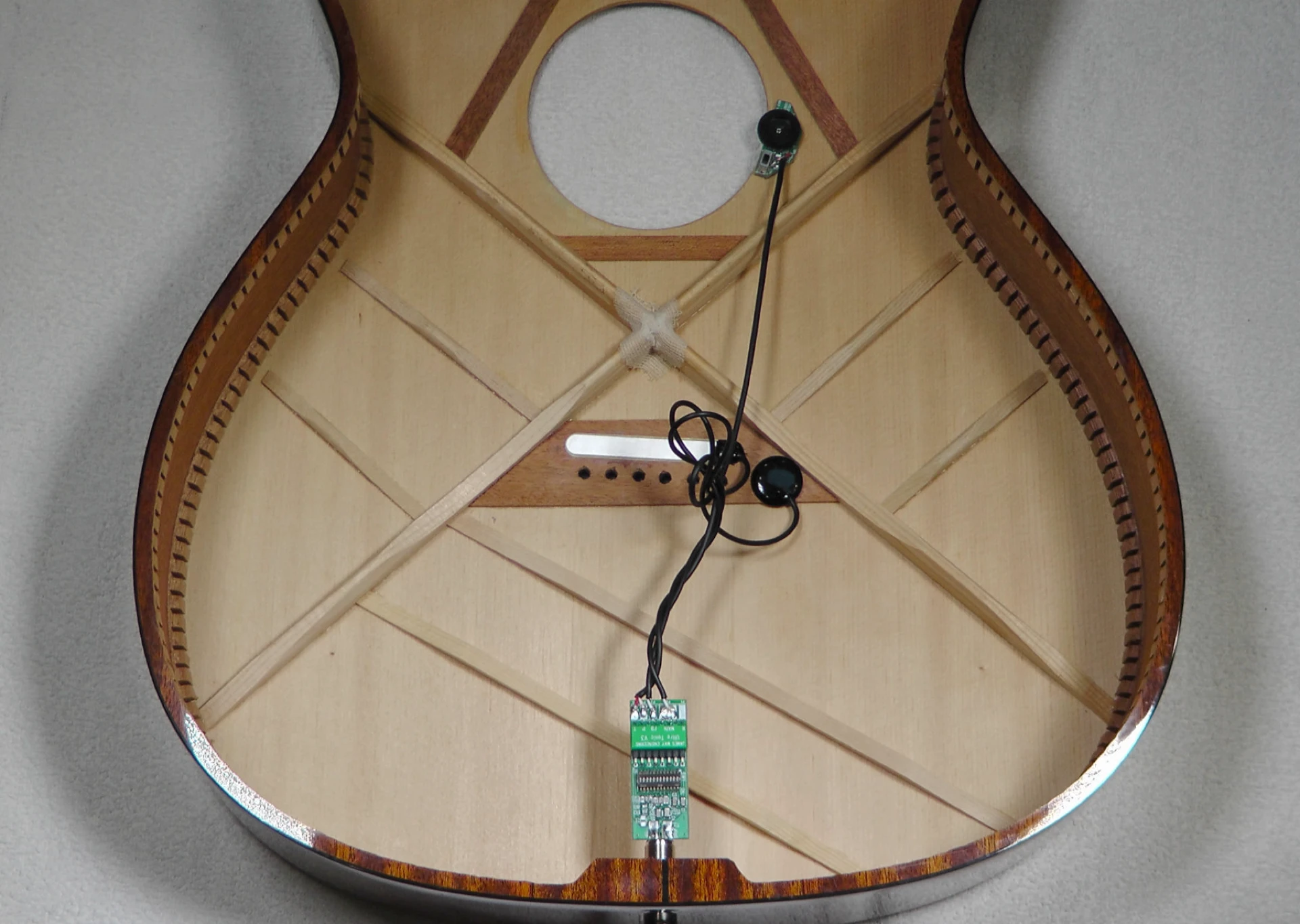
JME UTP V3 Complete Install (photo courtesy of JME)
The JME UTP Version 2 included 5 discs, and installation was very similar to installing K&K Pure pickups, where the disc-shaped transducers are affixed to the bridgeplate beneath the saddle position using gel cyanoacrylate (CA) glue.
Where the K&K Pure Mini comes with three (3) discs, Version 2 of the Ultra Tonic supplies a total of five (5) discs. Two discs are intended to bolster the (typically under-represented) 1st string. Two additional discs are spaced evenly beneath the saddle. A much larger disc is used to assist with feedback suppression.
JME UTP V2
I selected a 12 string as my test guitar for my very first installation of a JME pickup, thinking that if the new pickup could address the cacophony occurring within the soundbox (aka "lush overtones") that tend to overwhelm most pickups, it could handle anything.
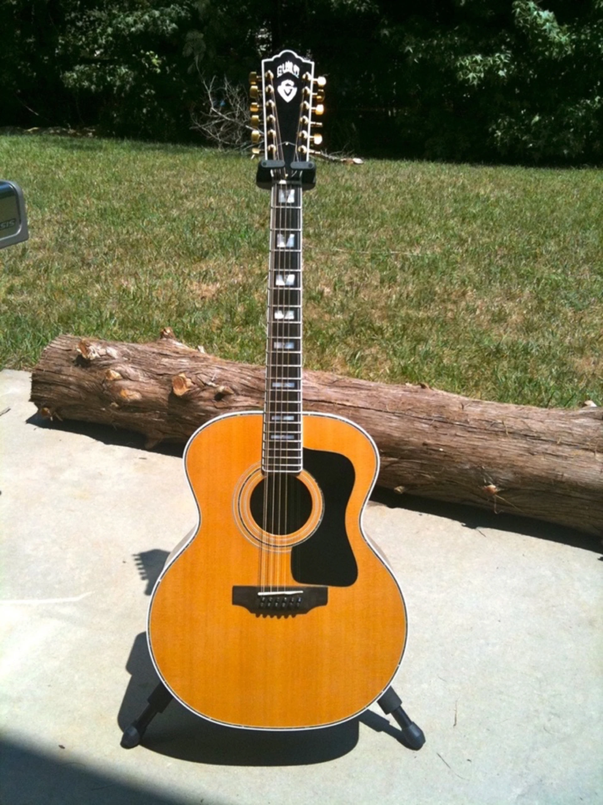
1976 Guild F-512
I studied the instructions supplied with the Ultra Tonic and, for my initial install, opted to fashion a jig to assist me with placement of the discs.
Custom Jig for Installing the Ultra Tonic
Three discs would be located between the pin holes, just as they would with a K&K install. Due to the proximity of the X-brace on this 12 string, I had to locate the fourth disc behind the saddle, behind the string hole.
The large suppression disc is intended to be attached toward the back of the bridgeplate on the bass strings side, well away from the saddle or strings. Inadvertently, I allowed the disc to drift a bit too far back and the glue "seized" in a position where the disc was overhanging the bridgeplate a bit too far. I obtained an additional disc from James May and replaced my mistake, attaching the new disc in the correct position.
JME UTP V2 in a 12 string
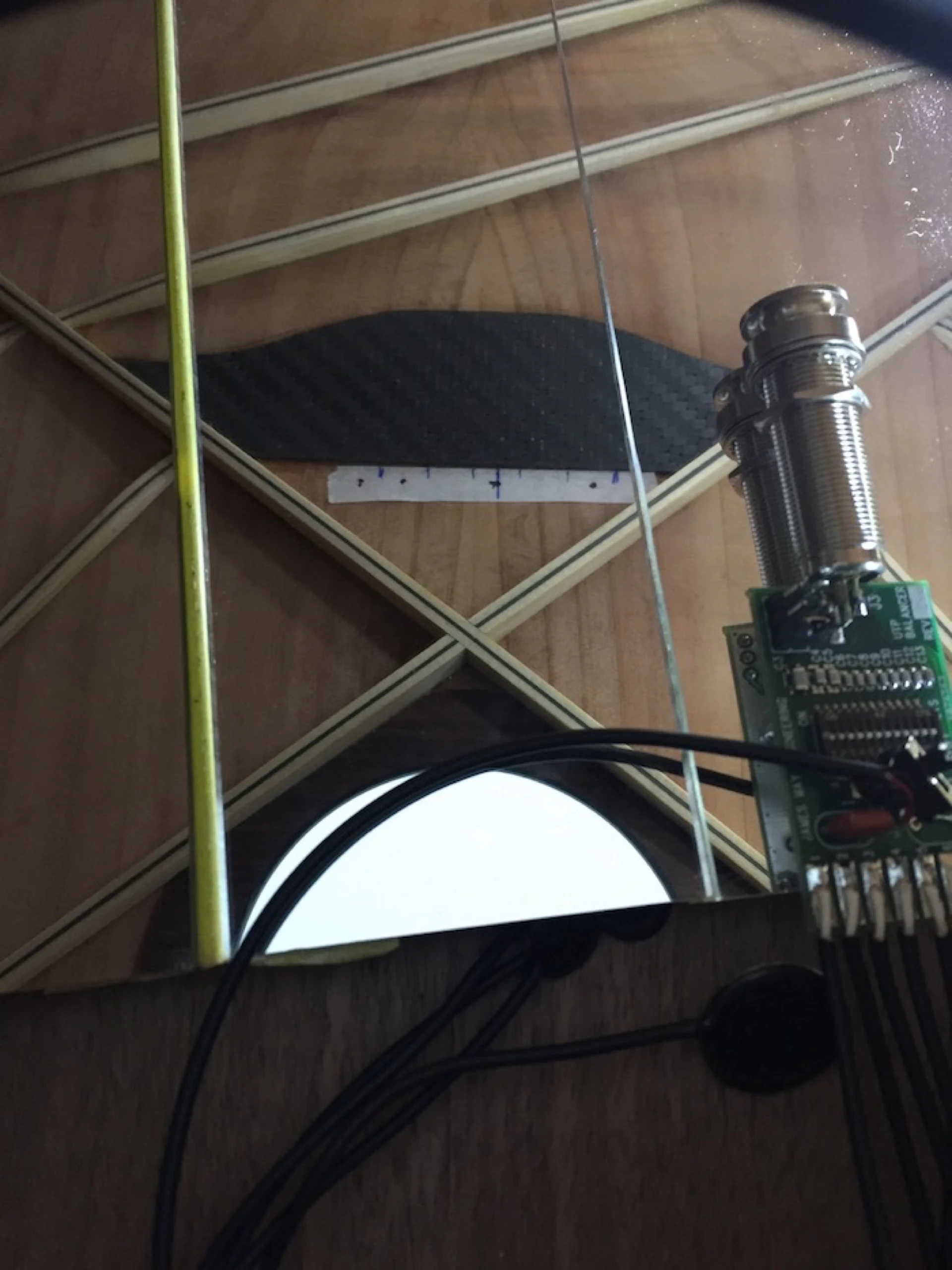
Here is a photo of an install inside one of my builds which has a pinless bridge and a carbon fiber bridgeplate. It is not possible to make use of a custom installation jig (such as the one I used on the 12 string), as there are no holes through the soundboard.
A piece of tape identifies the string and pickup positions. I am using an extremely low tack tape (I need to be able to easily remove it, later).
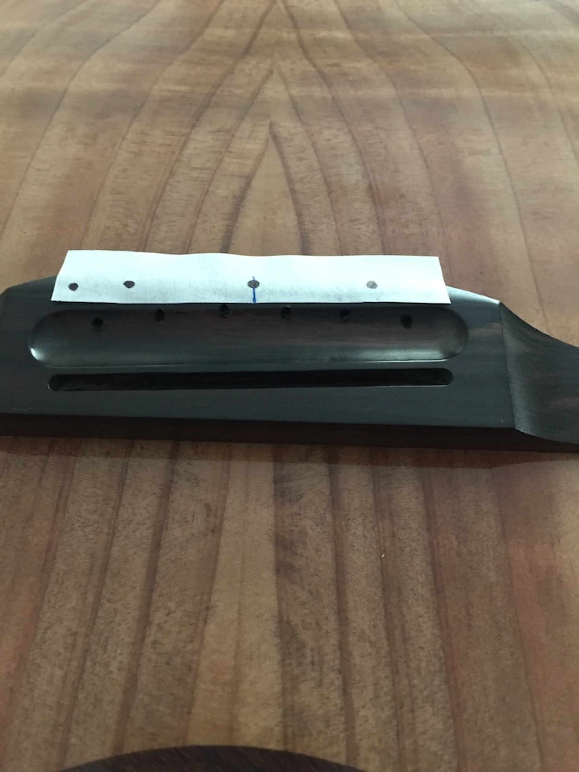
Tape on a pinless bridge
The tape is transferred to the underside of the soundboard (remember to think: upside down, backwards, in a mirror...easy!)
Tape inside
I have fashioned a high-tech pickup placement jig using bendable wire and double-stick (carpet) tape. If you have never attempted this before, I would suggest doing a few dry trial runs (no glue), as working in a mirror can produce unexpected results!
A word of caution: CA glue can permanently bond skin to a variety of materials, including SBT's and bridgeplates. If you are locating and securing these discs manually, you may want to wear a glove.
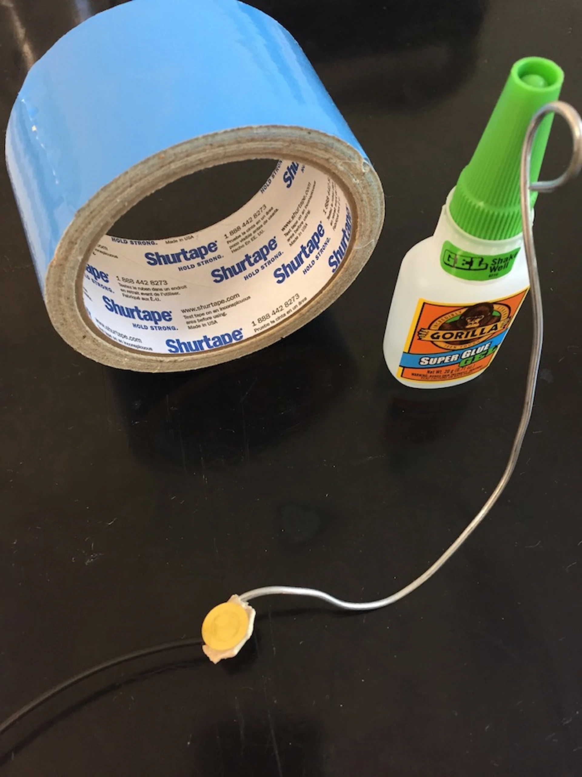
Wire jig, carpet tape, and CA glue
The sweet taste of Success!
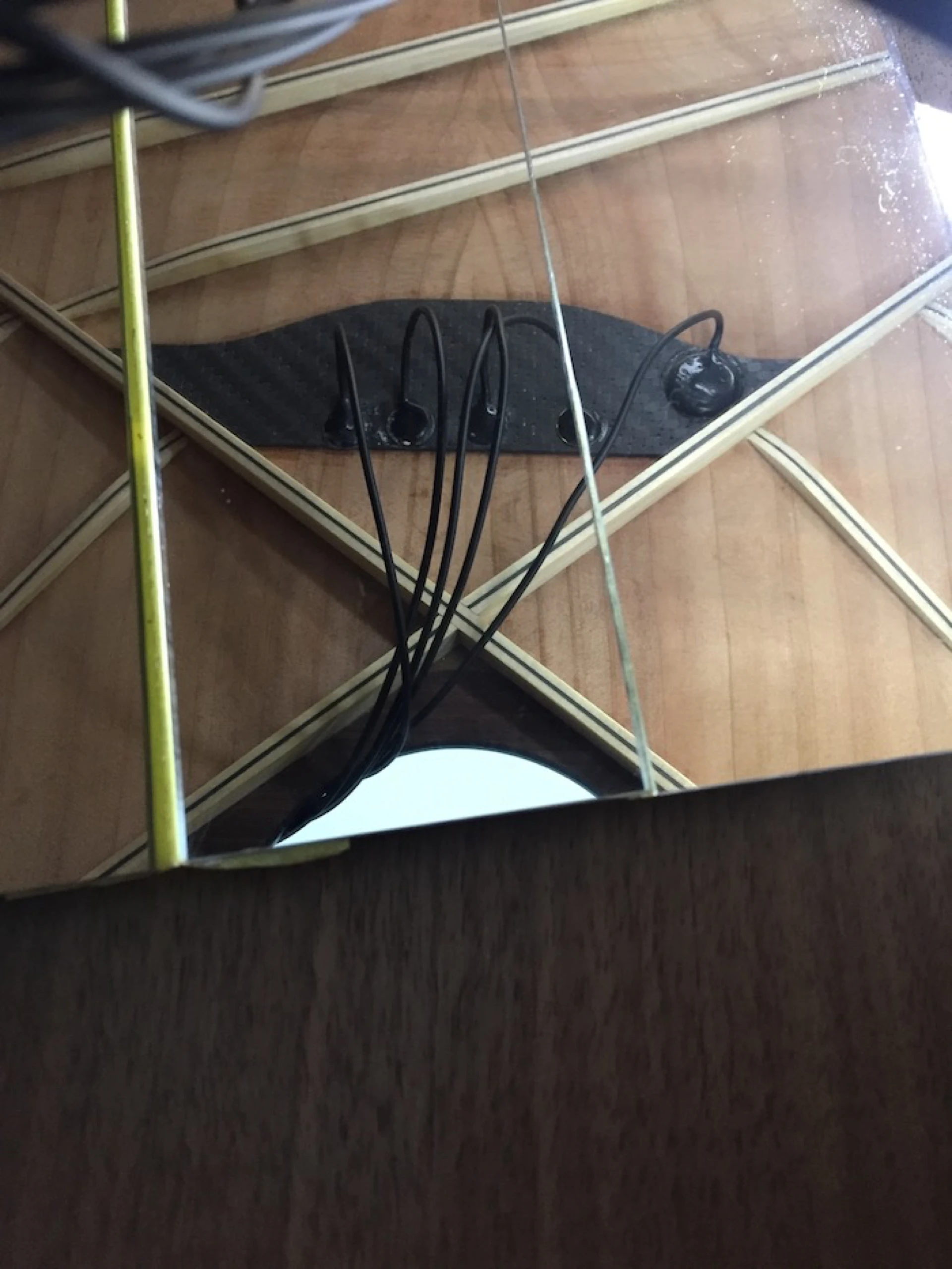
JME UTP V2 installed for pinless bridge
At this point the pickups are installed and I could simply secure the endpin jack, plug the guitar in to your favorite amp and play on, though I would not benefit from the onboard feedback suppression. The pickups sound very good, very “K&K”, with the notable benefit of improved volume on the 1st and 2nd strings.
At this point the pickups are installed and I could simply secure the endpin jack, plug the guitar in to my favorite amp and play on, though I would not benefit from the onboard feedback suppression.
This is the ideal time to test the efficacy of the 4th disc placement, to determine if the additional boost in volume of the 1st string is sufficient. With the shorting jumper removed, I slowly strum across the strings, listening to the overall volume level, particularly the volume of the 1st string. In the unlikely event it is too loud, the 4th disc can be either relocated, simply disconnected, or removed entirely.
The pickups sound very good, very “K&K”, with the notable benefit of improved volume on the 1st and 2nd strings (this is a 12 string.
In order to reap the rewards of the added circuitry accompanying the Ultra Tonic Pickup, it is necessary to take the pickup through the audio setup stage. This involves making adjustments to DIP switches found on the circuit board attached to the endpin jack.
The endpin jack and circuit board are left outside of the soundhole until audio setup is complete. I rested the jack on a folded paper towel, and taped it securely to the top.
The goal of the DIP switch selection process is to identify the best ratio or proportion for mixing in the larger, deliberately out-of-phase, suppression disc (the disc mounted farthest away from the strings) with the smaller, main discs (mounted beneath the string/saddle point of contact) so as to minimize the many potential resonances of the top plate (soundboard). This will result in a single DIP switch being set to the ON position, with all others switch OFF.
There are two approaches to setting the DIP switches:
Using testing equipment - V2 approach
The resonant frequency of the soundboard is hunted down with the aid of a tone generator (capable of producing a sine wave between 80 and 250Hz), an exciter, and a voltage meter (capable of reading single digit millivolts). Tone generators can be sophisticated standalone boxes or software applications run from your computer (I use the latter, and happen to like the free, aptly-named AudioTest by Katsura Shareware). An exciter is a speaker that is both capable of reproducing the needed tone (audio frequency) and is able to be put in contact with the soundboard of the guitar without doing damage. James May Engineering offers a simple exciter that works just fine.
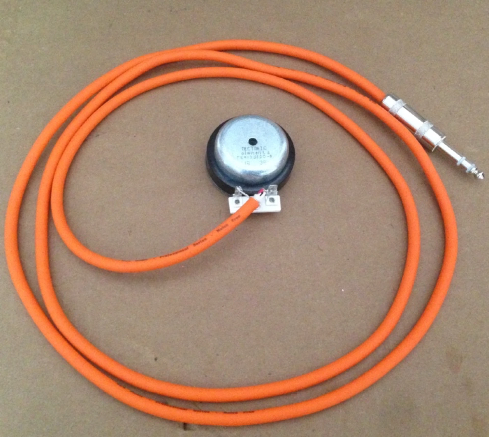
JME Exciter
The tone is generated. The exciter vibrates the guitar (audibly). A (milli) voltage meter, connected to the endpin jack, reads the output voltage of the pickup (created by the kinetic energy of the vibrating top). Locating the resonant frequency is a matter of altering the frequency of the sine wave (using the tone generator) and watching for the highest voltage reading on the meter. My 12 string happened to really move at 100Hz. Both 99 and 101Hz saw significantly lower output.
JME Feedback Suppression
With a shorting jumper (supplied with the pickup) installed in the middle position (position 2), a series of 12 DIP switches attached to the endpin jack are then switched ON and OFF, one at a time, watching the meter for the lowest output. These DIP switches are associated with that fifth (larger) disc, the one that was installed away from the saddle location. The DIP switch that produces the lowest output on meter wins, and gets set to ON for the rest of its life.
As with most tests, altering the parameters will affect the outcome. Changing the location of the pickups would necessitate a new test. While I have not done it (yet), I think it would be advisable to retest a double-stick tape installation after gluing the transducers in place, as things could change.
Once you are happy with the results, the endpin jack can be installed and the wires secured using any number of methods.
After completing my testing and setting the appropriate switch, re-testing the audio output of the pickup in this new condition was eye opening. The predominant 11th string volume was quieter. The boom-i-ness was gone! The highs were clean and the mid's no longer sounded like a piezo-electric pickup. Pretty impressive! I now have an acoustic guitar with a battery-free pickup system that can readily be plugged into most any sound reinforcement scenario and provide me with an amplified representation of my acoustic sound.
In my quest for "my guitar, only louder", I knew I could do even better by processing the signal through the ToneDexter. That signal is what you are hearing in the supplied recording.
Setting DIP switches by ear -
As with the method above, using testing equipment, it is necessary to walk through each DIP switch setting to locate the ideal switch to leave in the ON position. The shorting jumper needs to be installed in position 2 (the middle position). With all switches set to OFF, starting with switch 12 I flip the switch ON, strum across the strings, make a mental note of what I hear, flip the switch OFF, proceed to the next lower numbered switch, repeat the process, comparing the sounds of each setting. For optimal feedback suppression, I am looking for the setting where the bass response has been reduced the most. For the best overall sound, however, I may prefer to set the next adjacent switch to ON, setting my “optimal position” switch to OFF, instead. Through this brief trial and error process, setting one switch ON with all others set to OFF, and listening to the output I can quickly set up my Ultra Tonic pickup.
NOTE: If you carry a couple of extra tools with you to a performance (for endpin jack removal and for accessing the tiny DIP switches), you can readily make an adjustment to the switch settings, if it is ever needed.
I am impressed with the ingenuity behind the JME UTP's design. A straightforward installation that includes a volume control and onboard feedback suppression with no battery requirements, the Ultra Tonic is about as simple as it gets, while getting me what I need in a pickup. When paired with a ToneDexter, I believe I possess the closest representation to a mic’d guitar I have ever encountered. I have a complete pickup system that gets me closer to "My guitar, only louder", with the added benefit of reduced risk of feedback.
You can read more about the Ultra Tonic Pickup on the James May Engineering website » The Ultra Tonic pickup